Digital face-bow transfer technique using the dentofacial analyzer for dental esthetics and 2-D, 3-D smile design: A clinical report
July 6, 2018 / Categories: Digital Dentistry, Implant Dentistry

Brenes, Christian

Jurgutis, Larry

Babb, Courtney S.
Abstract
This article describes an effective and affordable technique for transferring a face-bow relation record to a virtual articulator for the proper orientation of the maxillary digital model using the Kois Dento-Facial Analyzer System. In complex esthetic and full-mouth rehabilitation cases, the orientation of the models to the articulator is crucial for the evaluation of excursive movements. The article elaborates on the necessary steps to use the face-bow transfer technique to design esthetic veneers based on a 2-D, 3-D smile design approach using a clinical case as an example of the protocol.
Keywords
Digital face-bow; digital wax-up; CAD/CAM; smile design; dentofacial analyzer.
Introduction
Digital workflows are becoming more popular and are in demand among clinicians and laboratory technicians owing to the increased incorporation of CAD/CAM tools into the daily practice. Digitization of records and data through cone beam computed tomography (CBCT) scans, intraoral scans and model manipulation contributes to better communication processes for diagnostics, treatment planning, designing and manufacturing in dentistry.
In past decades, clinicians and laboratory technicians have used analog articulators to simulate hinge and eccentric movements of the mandible, allowing for the fabrication of waxups and final restorations; the evaluation of occlusal function is fundamental to any dental treatment.1Weinberg LA. An evaluation of basic articulators and their concepts: Part I. Basic concepts. → J Prosthet Dent. 1963 Jul–Aug;13(4):622–44.2Weinberg LA. An evaluation of basic articulators and their concepts: Part II. Arbitrary, positional, semi adjustable articulators. → J Prosthet Dent. 1963 Jul–Aug;13(4):645–63. Face-bows were developed as a complement to different articulator systems to orient the maxillary arch to the center of rotation of the condyles in 3 planes of space and transfer the position to the articulator; similar movements can be reproduced for occlusal evaluation and diagnosis once the models have been properly mounted.3Weinberg LA. An evaluation of the face-bow mounting. → J Prosthet Dent. 1961 Jan–Feb;11(1):32–40.4Schallhorn RG. A study of the arbitrary center and the kinematic center of rotation for face-bow mountings. → J Prosthet Dent. 1957 Mar;7(2):162–9.
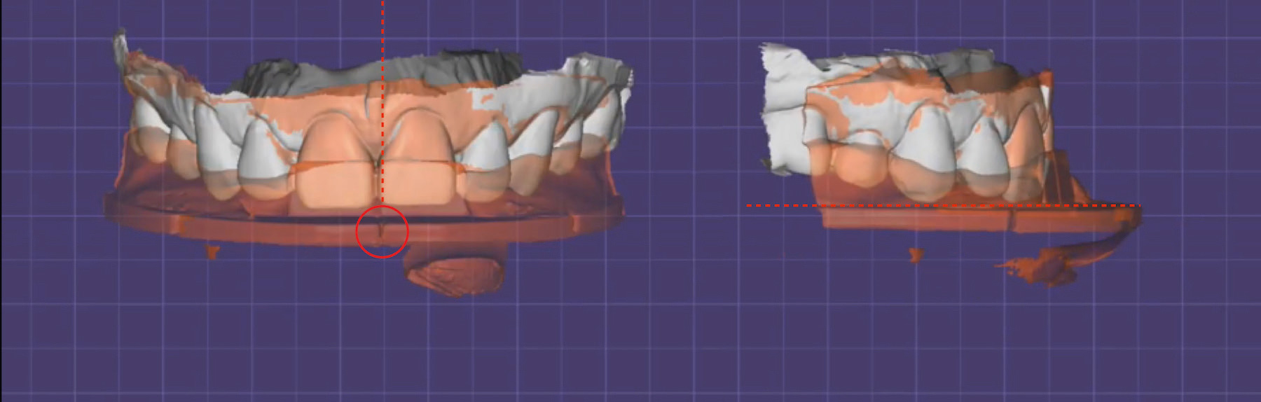
In recent years, the incorporation of CAD/ CAM technology has provided for more efficient protocols by automating processes and reducing manual labor. Intraoral scanners can digitize dental arches and register maxillomandibular relationships.5Ferracane JL, Giannobile WV. Novel biomaterials and technologies for the dental, oral, and craniofacial structures. → J Dent Res. 2014 Dec;93(12):1185–6.6Brenes C, Duqum I, Mendonza G. Materials and systems for all ceramic CAD/CAM restorations: a review of the literature. → CAD/CAM. 2016;3:10–15. Currently, many CAD/CAM systems include a virtual articulator simulatory module as a tool to simulate mandibular movements, which can be adjusted by using numerical values to represent condylar inclination, Bennett angle, vertical dimension, etc. The equivalent of analog mounted maxillary and mandibular casts still applies in the digital workflow for a proper evaluation; however, a major challenge has been to transfer the maxillary arch position without an analog tool such as a face-bow. A digital model behaves similarly to a floating object in space: The 3-D models are not accurately oriented in the x, y and z coordinates when they are digitally scanned, which makes identifying the facial midline and occlusal plane impossible without proper points of reference (Fig. 1). In complex esthetic and full-mouth rehabilitation cases, it is crucial to identify the midline and plane of occlusion to recognize any potential canting and occlusal problems.7Fradeani M. Evaluation of dentolabial parameters as part of a comprehensive esthetic analysis. → Eur J Esthet Dent. 2006 Apr;1(1):62–9.
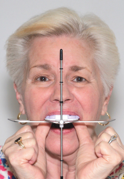
Panadent introduced a simplified system for transferring mounted study casts to the analog articulator, called the Kois Dento-Facial Analyzer System, or Dento-Facial Analyzer (DFA). The Dento-Facial Analyzer system is a device created by Dr. Kois and sold by Panadent (Panadent, California); the occlusal stand fits directly onto the magnetic mount of the Panadent articulator series; several companies have developed compatible occlusal stands to fit their articulators and similar systems. The device basically consists of a Fox plane with an adjustable middle rod (Fig. 2). An index tray is attached to the device to record the position of the maxillary arch using bite registration material and to transfer the patient’s occlusal plane and midline in the 3 planes of space to the analog articulator with a magnetic plate that attaches to an occlusal stand (Figs. 3 & 4). This allows mounting of the casts at a fixed distance of 100 mm, which is based on Kois’s research on average axis– incisal distance, which is substantiated by Bonwill’s equilateral triangle theory and Monson’s spherical theory.8Pitchford JH. A reevaluation of the axis-orbital plane and the use of orbitale in a facebow transfer record. → J Prosthet Dent. 1991 Sep;66(3):349–55.9Kois J, Kois D, Chayabutr Y. Occlusal errors generated at the maxillary incisal edge position related to discrepancies in the arbitrary horizontal axis location and to the thickness of the interocclusal record. → J Prosthet Dent. 2013 Nov;110(5):414–9.10Monson GS. Occlusion as applied to crown and bridge-work. → J Nat Dent Assoc. 1920 May;7(5):399–413.
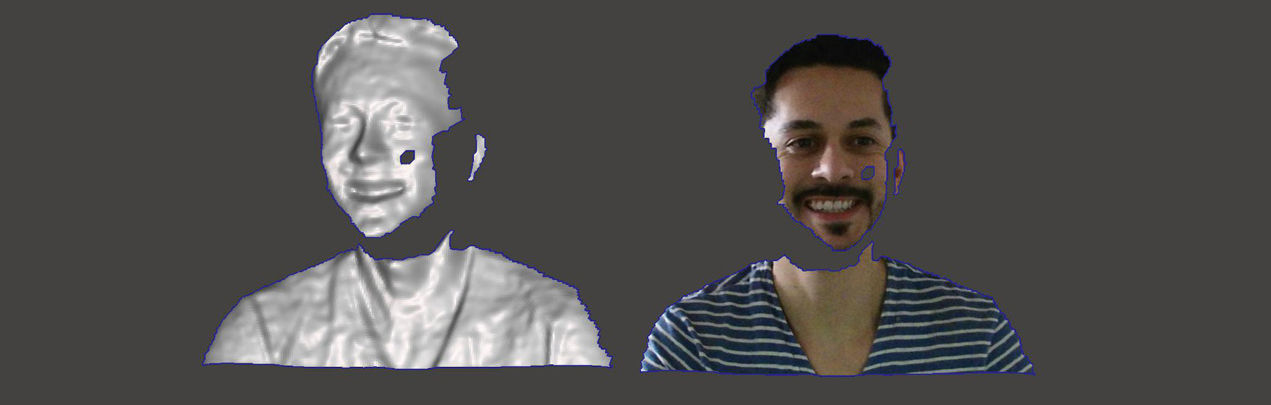
Different techniques have been proposed to transfer this information into the CAD software, but most are more time-consuming and complex, using full-volume CBCT data or 3-D facial scanners and different software to generate data able to align the maxillary scan to the skull.11Lam W, Hsung R, Choi W, Luk H, Pow EA. A 2-part facebow for CAD-CAM dentistry. → J Prosthet Dent. 2016 Dec;116(6):843–47.12Solaberrieta E, Garmendia A, Minguez R, Brizuela A, Pradies G. Virtual facebow technique. → J Prosthet Dent. 2015 Dec;114(6):751–5. Most affordable 3-D facial scanners (under $5,000) do not generate high-quality meshes that can be used to directly align dental casts. The scans are able to capture color and can confuse clinicians about the true quality of the underlying mesh; without the color, the quality of the underlying mesh is typically distorted and does not represent the shape of the actual object (Fig. 5). Moreover, 3-D facial scanners need to have reference markers to align the digital dental models to the facial scan, which makes the process more complicated than using an analog face-bow.
The technique described in this article overcomes these problems because it can align digital casts to the virtual articulator by using a bite scan in conjunction with the DFA. The facebow transfer technique is described as follows:
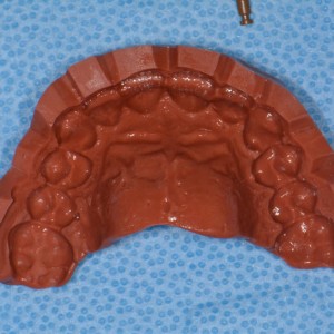
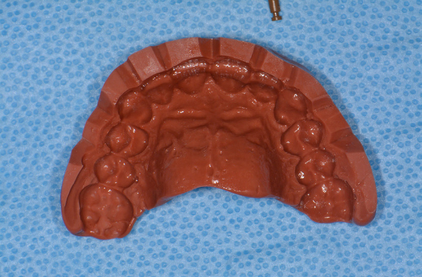
- Properly take a dentofacial record using the Kois DFA, aligning the middle rod to the midline of the patient and capturing the occlusal plane orientation with the Fox plane. Several materials, such as polyvinylsiloxane bite registration material, wax or impression compound, can be used on the plastic index tray.
- Scan the maxillary and mandibular arches with an intraoral scanner along with the bite record. The intraoral scan used in this case was PlanScan (Planmeca), Helsinki, Finland), but any intraoral scan or laboratory scan will work for its implementation (Figs. 6 & 7).
- Scan 1 bite record to align maxillary and mandibular arches and scan an additional bite record using the previous record captured with the plastic index tray on the maxillary cast. Since the plastic index tray was used as a record to capture the midline and plane of occlusion with the DFA, the external middle rod and the Fox plane are not needed for the bite record scan. The anterior middle notch in the index tray corresponds to the facial midline and the base of the tray corresponds to the occlusal plane (Fig. 8).
- Align all models and bite records in the software.
- Export all STL models and import to the design software or use it within the CAD software if the digital system has a CAD module integrated to start designing the anterior restorations or digital wax-up.
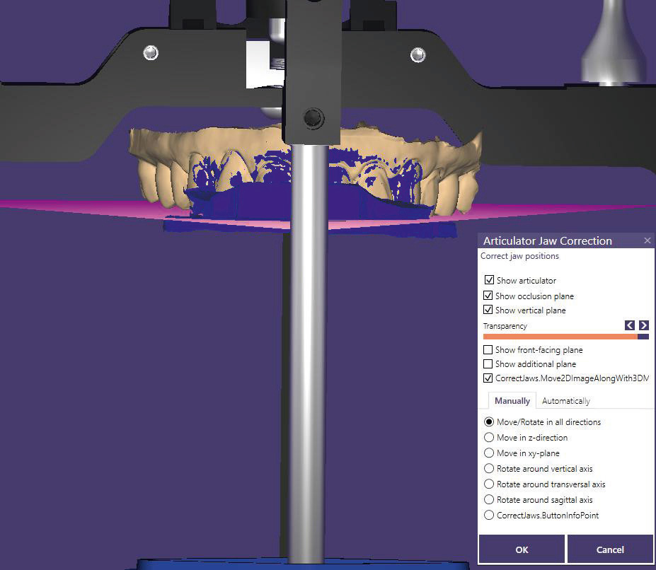
- If the CAD software has an articulator module available, the bite record can also be used; in this case, the exocad articulator module was used (exocad, Darmstadt, Germany). Click the boxes that display the horizontal and vertical planes of the articulator. Align the corresponding planes: midline notch of the index tray to the vertical plane of the articulator; and base of the index tray to the horizontal occlusal plane of the articulator (Figs. 9 & 10).
-

-
Fig. 1
Digital model imported into exocad dental software; the red lines illustrate the dental midline and occlusal plane estimated from tooth position without reference points.
-
-
Fig. 2
Patient holding the Kois Dento-Facial Analyzer System; the middle rod corresponds to the facial midline and the Fox plane is parallel to the interpupillary line.
-

-
Fig. 3
Index tray with bite registration material.
-

-
Fig. 4
Occlusal stand with index tray and dental model mounted.
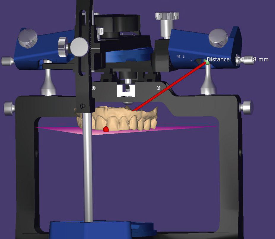
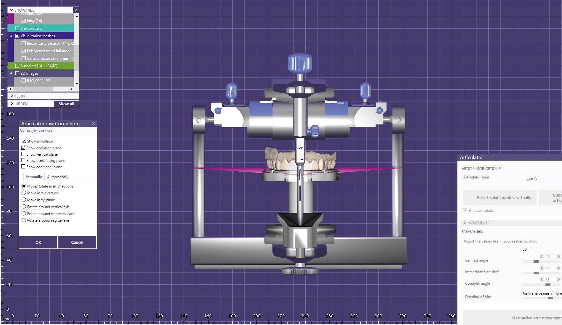
In addition to the basic alignment, the clinician has 2 different ways to correlate the anterior posterior distance of the digital model with the virtual articulator. The first option is available if the clinician already has a full-face skull CBCT (wide field of view, approximately 20 × 18 cm, standard resolution). The distance from the center of rotation of the condyles to the central incisors can be measured and reproduced in the articulator module (Fig. 11); the exocad DICOM viewer module can be used to measure the CBCT data and correlate the dental model scan of the maxillary arch. The second option is using the average axis–incisal distance reported by Kois’s research of 100–110 mm, which corresponds to the average anthropometric distance from the center of rotation of the condyles to the incisal edge of the maxillary central incisors; that is the distance traditionally used with the Panadent articulator models PCF and PSH and the occlusal stand used to mount the plastic index tray. A 3-D measurement ruler tool can be used in most CAD dental software to establish the distance and thus position the models.
-
-
Fig. 5
3-D facial scan showing the same mesh with and without color. The quality of the mesh without color can be appreciated and is not a good representation of the patient anatomy for registration purposes.
-
-
Fig. 6
Maxillary and mandibular models aligned in occlusion.
-
-
Fig. 7
Maxillary and mandibular models aligned displaying the bite record.
-
-
Fig. 8
Scanned model and index tray bite record showing the corresponding facial midline determined by the middle notch of the index tray and the occlusal plane determined by the base of the index tray.
-
-
Fig. 9
Frontal view of the model orientation based on the horizontal plane of the virtual articulator.Lateral view of the model orientation based on the vertical plane of the virtual articulator.
-
-
Fig. 10
Lateral view of the model orientation based on the vertical plane of the virtual articulator.
-
-
Fig. 11
Model orientation in the virtual articulator using the distance from the center of rotation of the condyles to the central incisors as the distance for proper mounting.
-
-
Fig. 12
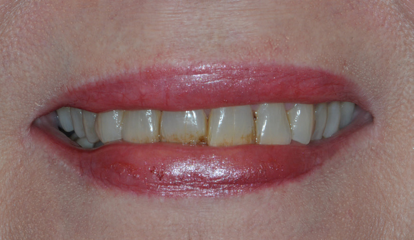
Preoperative smile photograph.
-
-
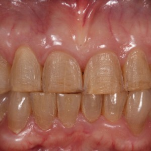
Fig. 13
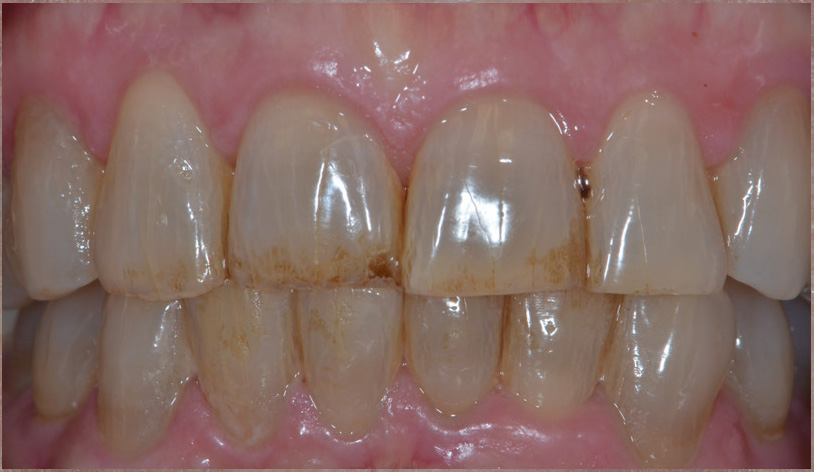
Preoperative intraoral photograph.
-
-
Fig. 14
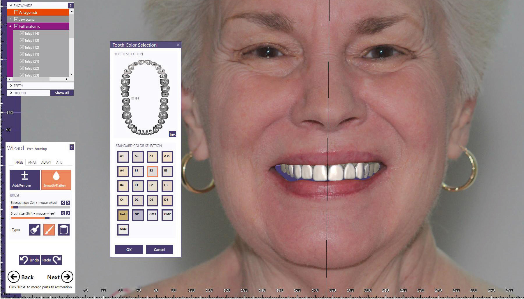
3-D smile design simulation.
This technique is beneficial in anterior esthetic cases and helpful in 3-D smile designs. The advantage of using a 2-D, 3-D integrated CAD design is that any request from the patient can be done instantly in the 3-D design, eliminating the need for a conventional wax-up, which takes hours, and minimizing the clinical time needed to obtain a cast, because the cast can be manufactured by means of a 3-D printer or milling machine, making the protocol extremely efficient. Furthermore, using 2-D images captured by photographic cameras or high-definition video cameras and superimposing them to 3-D data is the quickest and simplest approach. A 3-D facial scanner often cannot capture a smile in fractions of a second like a photograph can; instead, the patient has to hold the smile for several seconds, making it more difficult for clinicians to capture a true smile.
-
-
Fig. 15
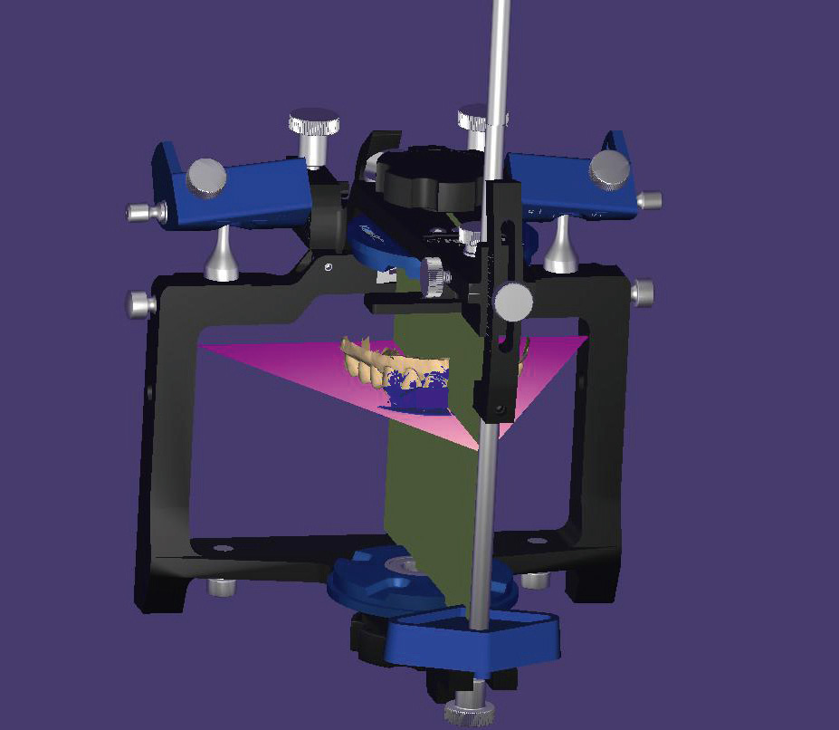
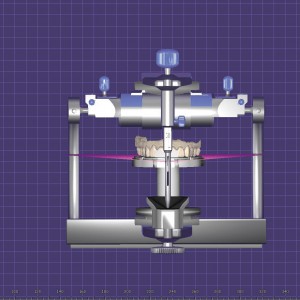
Virtual articulator.
-
-
Fig. 16
Putty jig made on the printed model for the mock-up.
-

-
Fig. 17
Mock-up used as reductions guide for tooth preparation.
-
-
Fig. 18
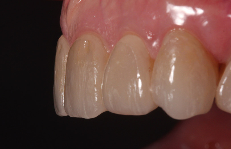
Intraoral photograph of conservative veneer preparations.
-
-
Fig. 19
Intraoral photograph of conservative veneer preparations.
Another advantage to using a virtual wax-up is the possibility of using cross-sectional views to visualize and measure the addition of restorative material prior to starting an invasive procedure. This is an extremely useful educational tool for minimally invasive techniques that can improve the appearance of the smile and at the same time offer a better prognosis by preserving tooth structure.13Gürel G. Porcelain laminate veneers: minimal tooth preparation by design. → Dent Clin North Am. 2007 Apr;51(2):419–31, ix.14Gurel G, Sesma N, Calamita MA, Coachman C, Morimoto S. Influence of enamel preservation on failure rates of porcelain laminate veneers. → Int J Periodontics Restorative Dent. 2013 Jan–Feb;33(1):31–9.
The purpose of this article is to describe the 2-D, 3-D smile design integration and its benefits in the provisionalization stage after using the digital face-bow transfer technique.
Clinical report
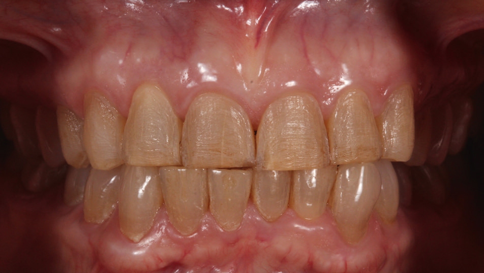
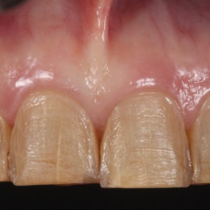
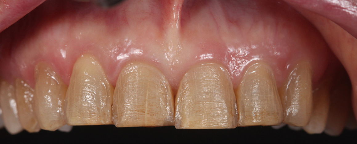
A 62-year-old woman presented to the Comprehensive Care Clinic at the Dental College of Georgia at Augusta University, Augusta, Georgia, U.S., with the chief complaint of worn and stained anterior teeth (Figs. 12 & 13). The patient was a smoker and reportedly smoked a pack per week. During the first appointment, clinical and radiographic examinations were done for proper diagnosis and formulation of a treatment plan. The clinical examination revealed attrition on the anterior teeth and maxillary premolars, stable periodontal health with probing depths of < 3 mm, and no endodontic lesions or pathology. A thorough occlusal analysis was done, with no significant findings. Maximum intercuspation position was coincidental with centric relation, and no alteration of the vertical dimension was diagnosed. After evaluation of the patient records, a set of intraoral and extraoral preoperative photographs was taken, along with a DFA record, which includes a record of the midline and occlusal plane based on facial esthetics (Fig. 14). Incisal edge position was determined first by adding composite to the left maxillary central incisor as a guide to establish the new length based on the evaluation of lips at rest and during smiling.15Vig RG, Brundo GC. The kinetics of anterior tooth display. → J Prosthet Dent. 1978 May;39(5):502–4. The composite restoration is not bonded to tooth structure and is only used to determine the esthetic incisal edge position during rest position, phonetics and smiling. Once the position is stablished the length is recorded for the future digital wax-up and the composite is removed. A prophylaxis was done during the appointment to treat some of the extrinsic staining present on the teeth.
-

-
Fig. 20
Milled IPS Empress CAD veneer blocks.
-
-
Fig. 21
Milled IPS Empress CAD veneers.
-
-
Fig. 22
Bonded veneers, lateral view.
-
-
Fig. 23
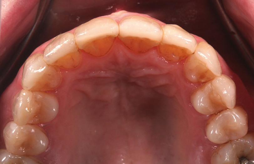
Bonded veneers, occlusal view.
With the diagnostic information acquired during the first appointment, the steps of aligning the models using the face-bow transfer technique with the DFA system were followed. A 2-D image of the patient was imported and aligned using match points to develop a 3-D functional virtual wax-up by adding restorative material to the maxillary anterior teeth and first premolars. A natural tooth library with squareshaped teeth similar to the patient’s natural anatomy was selected to create the virtual diagnostic wax-up to reproduce shape and texture. The dental software used in this case (exocad) also has a tooth color selection option to show a simulation of tooth shade, which facilitates the patient’s visual perception of the proposed treatment and improves treatment acceptance (Fig. 14). The design was evaluated functionally using the articulator module for excursive movements (Fig. 15).
The virtual 3-D smile design was shown to the patient at the second visit. She was able to visualize the possible results of the esthetic treatment and participate by giving feedback before any invasive procedures were initiated. No modifications were requested. The virtual wax-up was 3-D printed (MoonRay S, SprintRay, Los Angeles, Calif., U.S.) and a putty jig was created on the model to generate a mock-up for the patient using bis-acryl (Integrity, Dentsply Sirona, York, Pa., U.S.; Fig. 16) owing to its minimal shrinkage and excellent esthetic results. The mock-up has 2 functions. The first is to serve as an esthetic and functional prototype that enables the patient to visualize and experience the end result with a restorative material. Any modifications can be done at this stage because it is temporary and noninvasive. The second function is to work as a reduction guide once the patient has approved it; the reduction is created through the mock-up material and not through tooth structure (Fig. 17).
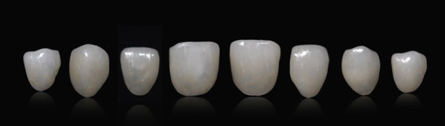
Minimally invasive preparation (0.5–0.8 mm facial reduction and 1.5 mm incisal/occlusal reduction) was done for the labial esthetic veneers, allowing for enamel preservation (Figs. 18 & 19). A final impression was taken and the 3-D virtual design was used as the preoperative digital model, since no modifications were done intraorally after verification. Leucite glass-ceramic blocks (IPS Empress CAD, Ivoclar Vivadent, Schaan, Liechtenstein) were milled for the final veneer restorations in-house using a milling machine (PlanMill 4.0, Planmeca; Figs. 20 & 21). Final characterization was done after glazing.
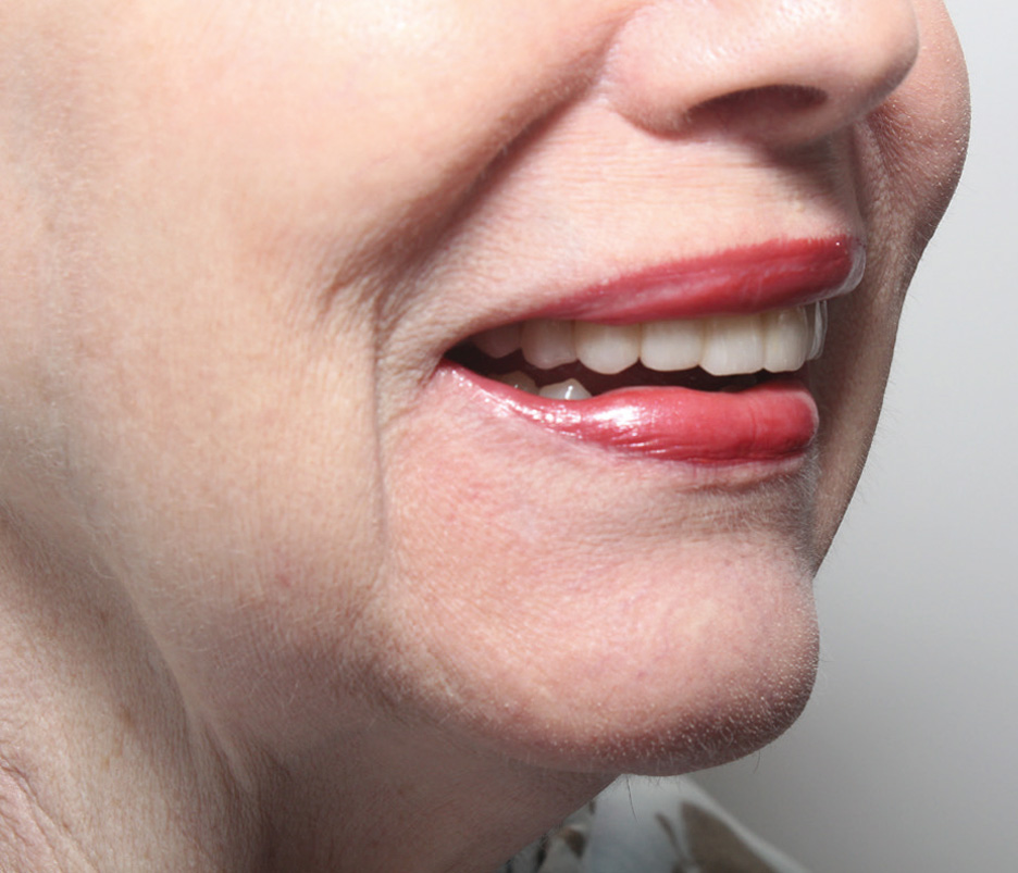
At the delivery appointment, an esthetic try-in was done prior to bonding the restorations. The patient approved the esthetics, marginal fit was verified, and the teeth and restorations were etched and bonded (Variolink Esthetic, Ivoclar Vivadent). The patient was extremely satisfied with the treatment outcome (Figs. 22–25). An occlusal guard was provided as part of the treatment plan. At the 1-year follow-up, the patient reported no complications.
-

-
Fig. 24
Postoperative frontal smile.
-
-
Fig. 25
Postoperative lateral smile.
Discussion
This article presents a simplified digital technique for transferring the face-bow information to the articulator. Transferring the position of the digital models in relation to the face is important to reproduce functional movements and have predictable esthetic results. Previous techniques using CBCT units require that the patient be submitted to unnecessary radiation to orient the models. In addition, other techniques using 3-D facial scanners require expensive hardware; most clinicians cannot justify this expense only for orientation purposes, and both of these methods require more time and are more complex in nature.
The face-bow transfer technique could also be used with edentulous patients by using occlusal rims as the reference points for the central incisors. The occlusal rim and the bite record with the plate would have to be scanned in order to register the meshes and align the edentulous models. However, this could be more technique-sensitive owing to the lack of stability of the bases.
While other bite forks can be used for the technique presented here, the authors highly recommend the DFA because of its ease of use. This technique is compatible with any virtual articulator, unlike analog articulators that require brand-compatible stands. This creates a universal digital transfer technique that can be efficiently shared digitally with any other clinician or laboratory technician. While additional studies are needed to validate accuracy and reproducibility, this technique has the potential to greatly improve the workflow of digital dentistry. The process could be made even more efficient with the implementation of a direct align algorithm in dental software upgrades and with the incorporation of jaw tracking devices and tracking scans. This technique is extremely useful in 3-D smile design cases or esthetic cases that require the visualization of facial landmarks such as the midline and plane of occlusion.
Conclusion
The digital face-bow transfer technique using the DFA system is a predictable, quick and easy method of scanning and aligning digital models to a virtual articulator without the need for expensive equipment.
Competing interests
The authors declare that they have no competing interests.
Acknowledgments
The authors would like to thank the following companies: exocad, Planmeca, SprintRay, and Roland for the support provided for education and research; their help was of tremendous value.

Interview
with Christian Brenes
Why did you conduct the research reported on in this paper?
For what reasons could others cite your paper?
How could your study’s findings have an impact on dentistry?
What is the relevance of your study’s findings to the daily practice of a dentist?
What are your recommendations for further investigation of the topic of your article?
References
| 1. | ↑ | Weinberg LA. An evaluation of basic articulators and their concepts: Part I. Basic concepts. → J Prosthet Dent. 1963 Jul–Aug;13(4):622–44. |
| 2. | ↑ | Weinberg LA. An evaluation of basic articulators and their concepts: Part II. Arbitrary, positional, semi adjustable articulators. → J Prosthet Dent. 1963 Jul–Aug;13(4):645–63. |
| 3. | ↑ | Weinberg LA. An evaluation of the face-bow mounting. → J Prosthet Dent. 1961 Jan–Feb;11(1):32–40. |
| 4. | ↑ | Schallhorn RG. A study of the arbitrary center and the kinematic center of rotation for face-bow mountings. → J Prosthet Dent. 1957 Mar;7(2):162–9. |
| 5. | ↑ | Ferracane JL, Giannobile WV. Novel biomaterials and technologies for the dental, oral, and craniofacial structures. → J Dent Res. 2014 Dec;93(12):1185–6. |
| 6. | ↑ | Brenes C, Duqum I, Mendonza G. Materials and systems for all ceramic CAD/CAM restorations: a review of the literature. → CAD/CAM. 2016;3:10–15. |
| 7. | ↑ | Fradeani M. Evaluation of dentolabial parameters as part of a comprehensive esthetic analysis. → Eur J Esthet Dent. 2006 Apr;1(1):62–9. |
| 8. | ↑ | Pitchford JH. A reevaluation of the axis-orbital plane and the use of orbitale in a facebow transfer record. → J Prosthet Dent. 1991 Sep;66(3):349–55. |
| 9. | ↑ | Kois J, Kois D, Chayabutr Y. Occlusal errors generated at the maxillary incisal edge position related to discrepancies in the arbitrary horizontal axis location and to the thickness of the interocclusal record. → J Prosthet Dent. 2013 Nov;110(5):414–9. |
| 10. | ↑ | Monson GS. Occlusion as applied to crown and bridge-work. → J Nat Dent Assoc. 1920 May;7(5):399–413. |
| 11. | ↑ | Lam W, Hsung R, Choi W, Luk H, Pow EA. A 2-part facebow for CAD-CAM dentistry. → J Prosthet Dent. 2016 Dec;116(6):843–47. |
| 12. | ↑ | Solaberrieta E, Garmendia A, Minguez R, Brizuela A, Pradies G. Virtual facebow technique. → J Prosthet Dent. 2015 Dec;114(6):751–5. |
| 13. | ↑ | Gürel G. Porcelain laminate veneers: minimal tooth preparation by design. → Dent Clin North Am. 2007 Apr;51(2):419–31, ix. |
| 14. | ↑ | Gurel G, Sesma N, Calamita MA, Coachman C, Morimoto S. Influence of enamel preservation on failure rates of porcelain laminate veneers. → Int J Periodontics Restorative Dent. 2013 Jan–Feb;33(1):31–9. |
| 15. | ↑ | Vig RG, Brundo GC. The kinetics of anterior tooth display. → J Prosthet Dent. 1978 May;39(5):502–4. |


Leave a Reply
Be the First to Comment!